On the Cluster Nodes, the hardware driver and additional kernel modules, user space libraries and the Node Manager will be installed. On the Cluster Management Node, the Network Manager and the cluster administration tool will be installed.
The software installation on windows is plug and play with the windows installer package (*.msi). The windows installer is executed on all Cluster Nodes in the system, either in parallel or one by one. The same installer image is used for all the Dolphin software components.
Start the software installation by double-clicking the installer image.
You will be met by a welcome message.
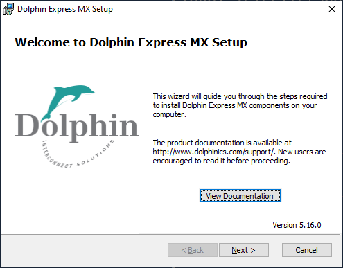
Click Next to select which components to install.
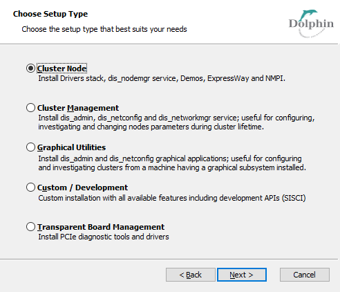
Choose your setup type.
Graphical Utilities installation can be used to.
Generate configuration files on a machine away from the running cluster.
Monitoring the Dolphin Admin GUI on a loosely connected machine.
Cluster Manager selection installs the centralized management tools. You may run the centralized management daemon, Dolphin Network Manager on one of the Cluster Nodes in the cluster, or on a separate machine that does not require Dolphin hardware.
Cluster Node installs drivers, the node manager daemon and other software that runs on the Dolphin Adapters.
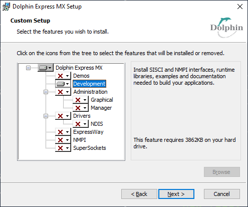
Custom / Development installation is typically used if you want to install more than one Dolphin Software module, e.g both Cluster Node and Cluster Management or the SISCI Development package on a separate machine, or if you want to de-select some components, or have other special requirements.
Transparent Board Management for transparent adapters where an EEPROM upgrade might be required or PCIe diagnostic tools are needed.
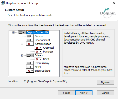
Select the features that match your installation an click next.
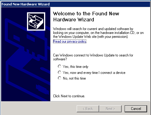
Since installing new hardware automatically generates some pop-ups that we do not need in the Dolphin installation you are kindly asked to Cancel these.
We ask you to trust our software even if we are part of the Windows logo program. Select Continue Anyway.
If your machine has a firewall installed, then you need to open up connections between the modules in the Dolphin Admin (Node Manager, Network Manager and dis_admin).
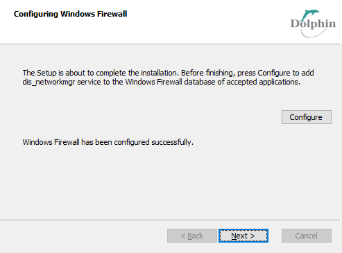
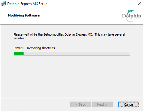
Click Next to complete the installation.
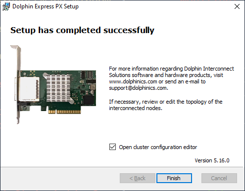
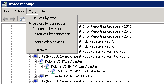
If the installation was successful the Dolphin Adapters will appear in Control Panel -> Administrative Tools -> Device Manager.
The Dolphin Network Configurator, dis_netconfig is only opened if the Management or Graphical tools are selected. Typically the Dolphin Network Manager, dis_networkmgr, is started when the you have saved the interconnect topology with dis_netconfig.
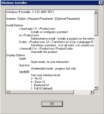
It is possible to run the Dolphin windows installer package from the command line as well. The same installer image is used for all Dolphin software components. When you install from the command line you use the msiexec command.
The command line switch to msiexec is /i for install. If you also use the ADDLOCAL switch you may select specific modules that you want to install. Running without the ADDLOCAL switch installs all modules. These are the modules that you may preselect:
Drivers
NDIS
SuperSockets
Administration
Manager
Graphical
Demos
Development
NMPI
ExpressWay
Another useful switch combination to msiexec is /qb which lets you run without opening the windows installer in Section 2.1, “Running the Dolphin Installer”. Run msiexec without options for documentation.
A typical Node installation contains these components:
Drivers
Demos
NMPI
ExpressWay
C:\> msiexec /i Dolphin_eXpressWare-Windows-NT63-x86_64-MX-DIS_RELEASE_5_16_0_APR_21_2020.msi
ADDLOCAL=Drivers,Demos,NMPI,ExpressWay /qb
The installation is not 100% silent. You need to perform the step described in Figure 4.7, “Windows Installer: Continue Anyway on Windows XP and Windows Server 2003”.
A rich Cluster Management Node user would typically select all packages:
C:\>msiexec /i Dolphin_eXpressWare-Windows-NT63-x86_64-MX-DIS_RELEASE_5_16_0_APR_21_2020.msi
/qb
The installation is not 100% silent. You need to perform the step described in Figure 4.7, “Windows Installer: Continue Anyway on Windows XP and Windows Server 2003” and Figure 4.6, “Windows Installer: Cancel Wizard on Windows XP and Windows Server 2003”.
If you use the command line tools to install the Cluster Management component, then you need to start the Network Manager manually:
C:\>sc.exe start dis_networkmgr

SERVICE_NAME: dis_networkmgr
        TYPE               : 10  WIN32_OWN_PROCESS
        STATE              : 4  RUNNING
                                (STOPPABLE,NOT_PAUSABLE,ACCEPTS_SHUTDOWN)
        WIN32_EXIT_CODE    : 0  (0x0)
        SERVICE_EXIT_CODE  : 0  (0x0)
        CHECKPOINT         : 0x0
        WAIT_HINT          : 0x0
        PID                : 3284
        FLAGS              :

C:\>
If you use the command line tools to install the Cluster Management component. The you need to start the Network Manager manually:
C:\>sc.exe start dis_networkmgr

SERVICE_NAME: dis_networkmgr
        TYPE               : 10  WIN32_OWN_PROCESS
        STATE              : 4  RUNNING
                                (STOPPABLE,NOT_PAUSABLE,ACCEPTS_SHUTDOWN)
        WIN32_EXIT_CODE    : 0  (0x0)
        SERVICE_EXIT_CODE  : 0  (0x0)
        CHECKPOINT         : 0x0
        WAIT_HINT          : 0x0
        PID                : 3284
        FLAGS              :

C:\>
The Cluster Nodes get installed and drivers and the node manager are started. Then, the basic packages are installed on the Cluster Management Node, and the dis_netconfig application is launched to create the required configuration files %WinDir%\system32\drivers\etc\dis\dishosts.conf and %WinDir%\system32\drivers\etc\dis\networkmanager.conf if they do not already exist.
For typical problems at this point of the installation, please refer to Chapter 14, FAQ.
The Dolphin Network Configurator, dis_netconfig is a GUI tool that helps gathering the cluster configuration (and is used to create the cluster configuration file %WinDir%\system32\drivers\etc\dis\dishosts.conf and the Network Manager configuration file %WinDir%\system32\drivers\etc\dis\networkmanager.conf). A few global interconnect properties need to be set, and the position of each Cluster Node within the interconnect topology needs to be specified.
When dis_netconfig is launched, it first displays a dialog box where the global interconnect properties need to be specified (see Figure 4.12, “Cluster Edit dialog of dis_netconfig”).
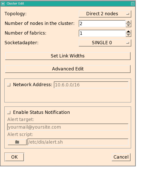
In the upper half of the Cluster Edit dialog, you need to specify the interconnect topology that you will be using with your cluster. If dis_netconfig is launched by the installation script, the script tries to set these values correctly, but you need to verify the settings.
Then, specify the Number of Cluster Nodes in your cluster.
The Number of fabrics needs to be set to the minimum number of adapters in every Cluster Node (typically, this value is 1).
The Socketadapter setting determines which of the available adapter is used for SuperSockets:
SINGLE 0: only adapter 0 is used
SINGLE 1: only adapter 1 is used (only valid for more than one fabric)
Channel Bonding: SuperSockets distributes the traffic across both adapters 0 and 1 (only valid for more than one fabric)
NONE: SuperSockets should not be used.
You then need to Set Link Widths for each Cluster Node. This can be set to x4, x8 or x16. The default is x8. The value must be set to x4 or x8 if a x4 or x8 cable is used, otherwise the low level driver will try to reset the link to establish a x8 or x16.
The Advanced Edit option does not need to be changed: the session between the Cluster Nodes should typically always be set up automatically.
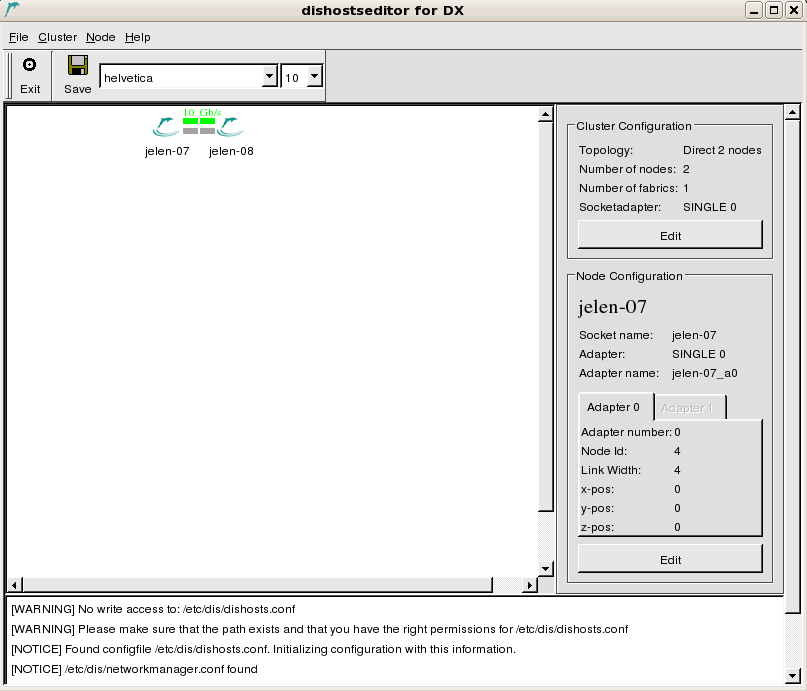
In the next step, the main pane of the dis_netconfig will present the Cluster Nodes in the cluster arranged in the topology that was selected in the previous dialog. To change this topology and other general interconnect settings, you can always click in the Cluster Configuration area which will bring up the Cluster Edit dialog again.
If the font settings of your X server cause dis_netconfig to print unreadable characters, you can change the font size and the type with the drop-down box at the top of the windows, next to the floppy disk icon.
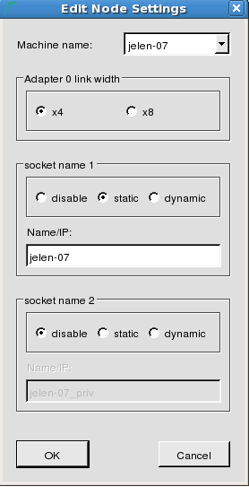
In the Node dialog you specify if you want to use 4, 8 or 16 PCI Express lanes. The value must be set to x4 if you are using a x4 to x8 transition cable or a x4 fiber cable.
The serial number field specifies which adapter will have its index unchanged in the adapters' array. If two cards are interchanged, or if one of the two is replaced, then the card with its serial number fully specified is guaranteed to have the same adapter number. Applications can continue to use the card based on its adapter number.
After you have assigned the correct hostname to this machine, you may need to configure SuperSockets on this Cluster Node. If you selected the Network Address in the cluster configuration dialog (see above), then SuperSockets will use this subnet address and will not allow for editing this property on the Cluster Nodes. Otherwise, you can choose between 3 different options for each of the currently supported 2 SuperSockets accelerated IP interfaces per Cluster Node:
- disable
Do not use SuperSockets. If you set this option for both fields, SuperSockets can not be used with this Cluster Node, although the related kernel modules will still be loaded.
- static
Enter the hostname or IP address for which SuperSockets should be used. This hostname or IP address will be statically assigned to this physical Cluster Node (its PCI Express interconnect adapter).
Choosing a static socket means that the mapping between the Cluster Node (its adapters) and the specified hostname/IP address is static and will be specified within the configuration file
dishosts.conf. All Cluster Nodes will use this identical file (which is automatically distributed from the Cluster Management Node to the Cluster Nodes by the Network Manager) to perform this mapping.This option works fine if the Cluster Nodes in your cluster don't change their IP addresses over time and is recommend as it does not incur any name resolution overhead.
- dynamic
Enter the hostname or IP address for which SuperSockets should be used. This hostname or IP address will be dynamically resolved to the PCI Express interconnect adapter that is installed in the machine with this hostname/IP address. SuperSockets will therefore resolve the mapping between adapters and hostnames/IP addresses dynamically. This incurs a certain initial overhead when the first connection between two Cluster Nodes is set up and in some other specific cases.
This option is similar to using a subnet but resolves only the explicitly specified IP addresses (for all Cluster Nodes) and not all possible IP addresses of a subnet. Use this option if Cluster Nodes change their IP addresses i.e. in a fail-over setup.
You should now generate the cabling instructions for your cluster. Please do this also when the cables are actually installed: you really want to verify if the actual cable setup matches the topology you just specified. To create the cabling instruction, choose the menu item -> . You can save and/or print the instructions. It is a good idea to print the instructions so you can take them with you to the cluster.
If the cables are already connected, please proceed with section Section 2.5.2, “Verifying the Cabling”.
Note
In order to achieve a trouble-free operation of your cluster, setting up the cables correctly is critical. Please take your time to perform this task properly.
The cables can be installed while Cluster Nodes are powered up.
Please proceed by connecting the PCIe cables
Additional information can be found in the Users Guides for the interconnected products.
Important
A green link LED indicates that the link between the output plug and input plug could be established and synchronized. It does not assure that the cable is actually placed correctly! It is therefore important to verify once more that the cables are plugged according to the cabling instructions generated by the dis_netconfig!
If a pair of LEDs do not turn green, please perform the following steps:
Power-cycle the Cluster Nodes with the orange LEDs according to Chapter 14, FAQ,.
Contact contact Dolphin support, www.dolphinics.com, if you can not make the LEDs turn green after trying all proposed measures.
When you are done connecting the cables, no more user interaction is required. Please confirm that all cables are connected and all LEDs are green, and the installation will proceed. The Network Manager will be started on the Cluster Management Node, configuring all Cluster Nodes according to the configuration specified in dishosts.conf.
If you still fail to install the software successfully, refer to Chapter 5, Interconnect Maintenance.If you still fail to install the software successfully, you should contact Dolphin support, www.dolphinics.com. Please provide all installation log files. To get the installation logs, please run each MSI with /l*xv log_install.txt switch:
C:\>Dolphin_eXpressWare-Windows-NT63-x86_64-MX-DIS_RELEASE_5_16_0_APR_21_2020.msi /l*xv
C:\log_install.txt
Please also include the configuration files that can be found in %WinDir%\system32\drivers\etc\dis on the Cluster Management Node.
Dolphin provides a graphical tool named dis_admin. dis_admin serves as a tool to visually view the status and run diagnostics on your PCIe network. It shows an overview of the status of all adapters and links of a cluster and allows to perform detailed status queries. It also provides means to manually control the interconnect, inspect and set options and perform interconnect tests. For a complete description of dis_admin, please refer to Appendix A, dis_admin Reference. Here, we will only describe how to use dis_admin to verify the newly installed PCI Express network.
You can use dis_admin on any machine that can connect to the Network Manager on the Cluster Management Node via a standard TCP/IP socket. You have to make sure that connections towards the Cluster Management Node using the ports 3444 (Network Manager) and 3443 (node manager) are possible (potentially firewall settings need to be changed).
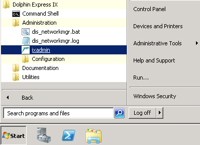
Start dis_admin from the Windows Menu
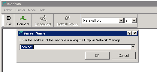
After it has been started, you will need to connect to the Network Manager controlling your cluster. Click the button in the tool bar and enter the appropriate hostname or IP address of the Network Manager.
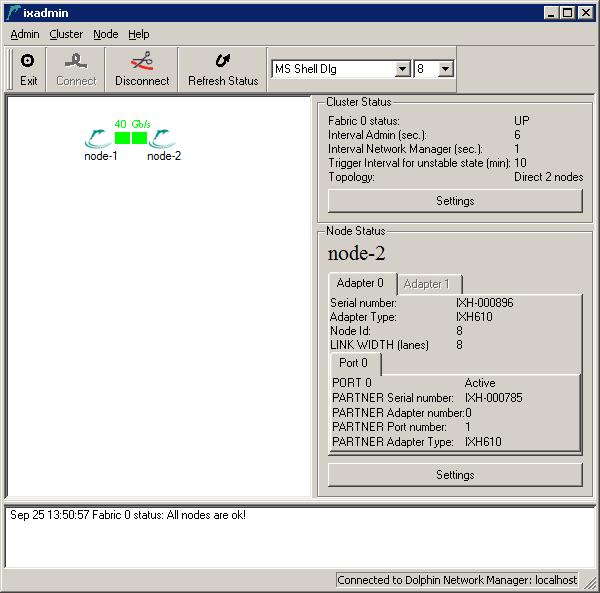
dis_admin will present you a graphical representation of the cluster Cluster Nodes and the interconnect links between them.
Normally, all Cluster Nodes and interconnect links should be shown green, meaning that their status is OK. This is a requirement for a correctly installed and configured cluster and you may proceed to Section 2.7.4, “PCIe connection Test”.
If a Cluster Node is plotted red, it means that the Network Manager can not connect to the node manager on this Cluster Node. To solve this problem:
Make sure that the Cluster Node is powered and has booted the operating system.
Verify that the node manager service is running:
>sc.exe query dis_nodemgr
should tell you that the node manager is running. If this is not the case:
Try to start the node manager with the startup script in the windows menu. Optionally:
>sc.exe start dis_nodemgr
If the node manager fails to start, please see %WinDir%\system32\drivers\etc\dis\log\dis_nodemgr.log
dis_admin can validate that all PCIe connections are connected according to the configuration that was specified in the dis_netconfig, and which is now stored in %WinDir%\system32\drivers\etc\dis\dishosts.conf on all Cluster Nodes and the Cluster Management Node. To perform the connection test, select . This test runs for only a few seconds and will verify that the Cluster Nodes are connected according to the configuration provided by the dis_netconfig.
Warning
Running this test may stop the normal traffic over the interconnect as the routing may be changed to fully test the network.
If the test detects a problem, it will inform you that Cluster Node A can not communicate with Cluster Node B. You will get more than one error message if the problem is caused by problem with a central switch etc.:
Try to fix the first reported problem by tracing the cable connections from Cluster Node A to Cluster Node B:
Verify that the cable connections:
Look up the path of cable connections between Cluster Node A and Cluster Node B in the Cabling Instructions that you created (or still can create at this point) using dis_netconfig.
When you arrive at Cluster Node B, do the same check for the path back from Cluster Node B to Cluster Node A.
Along the path, make sure:
That each cable plug is securely fitted into the socket of the adapter.
If you are using the multi port MXH830 adapter, verify each cable plug is connected to the right ports (1, 2, 3 or 4) as indicated by the cabling instructions.
If you can't find a problem for the first problem reported, verify the connections for all following pairs of Cluster Node reported bad.
After the first change, re-run the cable test to verify if this change solves all problems. If this is not the case, start over with this verification loop.
Dolphin provides a console tool named dis_admin_commandline. dis_admin_commandline shows an overview of the status of all nodes and links of a cluster and allows to perform a limited set of queries.
dis_amin_commandline will be installed on the Cluster Management Node if you select to include the Management or Graphical package.
Any command that is passed to dis_admin_commandline must be preceded by -cluster <frontend_machine_name> -fabric <adapter_number> . The full list of commands is printed when the program is started with no command line arguments.
Here are the most common commands used for inspection:
get-cluster-infoshows the cluster status and the topology dimensions.get-fabric-stateprints on one line the cluster status.application <name_of_application> <node1> <node2> <node...>runs one of the predefined applications on the specified Cluster Nodes. The supported applications are: alltoall, sciconntest, latency_bench, scipp, scibench2, dma_bench, intr_benchdis_admin_commandline-cluster node-3 -fabric 0 application sciconntest node-3 node-4 Feb 10 19:17:18 Started an application on node-3,node-4. Feb 10 19:17:18 This might take some time. Timeout is 55 seconds. [RESULT FROM RUNNING CMD ON SELECTED NODES] [node-3]: C:\Program Files\Dolphin Express\demo\sciconntest compiled Feb 10 2012 : 00:08:07 Response from remote node 8 ---------------------------- Local node-id : 4 Local adapter no. : 0 Segment size : 8192 MinSize : 4 Time to run (sec) : 10 Idelay : 0 No Write : 0 Loopdelay : 0 Delay : 0 Bad : 0 Check : 0 Mcheck : 0 Max nodes : 256 rnl : 1 Callbacks : Yes ---------------------------- Local segment (id=8, size=8192) is created. Local segment (id=8, size=8192) is shared. Connecting to 1 nodes Connect to remote segment, node 8 Remote segment on node 8 is connected. SCICONNTEST_REPORT NUM_TESTLOOPS_EXECUTED 155 NUM_NODES_FOUND 1 NUM_ERRORS_DETECTED 0 node 8 : Found node 8 : Number of failures : 0 node 8 : Longest failure : 0.00 (ms) SCICONNTEST_REPORT_END SCI_CB_DISCONNECT:Segment removed on the other node disconnecting..... The local segment is set to unavailable The local segment is removed [node-4]: C:\Program Files\Dolphin Express\demo\sciconntest compiled Feb 10 2012 : 00:08:07 Response from remote node 4 ---------------------------- Local node-id : 8 Local adapter no. : 0 Segment size : 8192 MinSize : 4 Time to run (sec) : 10 Idelay : 0 No Write : 0 Loopdelay : 0 Delay : 0 Bad : 0 Check : 0 Mcheck : 0 Max nodes : 256 rnl : 1 Callbacks : Yes ---------------------------- Local segment (id=4, size=8192) is created. Local segment (id=4, size=8192) is shared. Connecting to 1 nodes Connect to remote segment, node 4 Remote segment on node 4 is connected. SCICONNTEST_REPORT NUM_TESTLOOPS_EXECUTED 154 NUM_NODES_FOUND 1 NUM_ERRORS_DETECTED 0 node 4 : Found node 4 : Number of failures : 0 node 4 : Longest failure : 0.00 (ms) SCICONNTEST_REPORT_END The local segment is set to unavailable The local segment is removed SCI_CB_DISCONNECT:Segment removed on the other node disconnecting..... [DONE RUNNING CMD ON SELECTED NODES]get-interruptinforetrieves the interrupt counters on all Cluster Nodes.dis_admin_commandline -cluster node-3 -fabric 0 get-interruptinfo Feb 10 18:09:52 Started cmd get-interruptinfo on all nodes. node-3: No of total interrupt : 313 No of doorbell intterupts : 2 No of message interrupts : 61 No of switch events : 95 No of link up events : 28 No of link down events : 28 No of uncorrectable error events : 39 No of correctable error events : 0 No of unclaimed interrupts : 156 node-4: No of total interrupt : 118 No of doorbell intterupts : 1 No of message interrupts : 61 No of switch events : 56 No of link up events : 28 No of link down events : 28 No of uncorrectable error events : 0 No of correctable error events : 0 No of unclaimed interrupts : 0 Total correctable errors = 0, uncorrectable errors = 39
After the PCI Express hard- and software has been installed and tested, you can configure your cluster application to make use of the increased performance.
Applications that consume Winsock2 calls for communication can be accelerated by SuperSockets without modifying the application binaries. For details, please refer to Section 2, “Make Generic Windows Applications use SuperSockets”.
Native SISCI applications use the SISCI API to use the PCI Express hardware features like transparent remote memory access, DMA transfers or remote interrupts. The SISCI library sisci_api.dll is installed on all Cluster Nodes by default. Any application that uses the SISCI API will be able use the PCI Express interconnect immediately when the network is configured and operational.
To compile and link SISCI applications, select the Development feature from the MSI graphical interface for installation.
A development project that uses the sisci_api.h interface must include 2 paths [InstallDirectory]\Dolphin Express MX\Include and [InstallDirectory]\Dolphin Express MX\Include\dis and link to the 64 Bit sisci_api.lib import library located in [InstallDirectory]\Dolphin Express MX\Lib\x64 or the 32 Bit sisci_api.lib import library located in [InstallDirectory]\Dolphin Express MX\Lib\x86.
Several examples are installed at: [InstallDirectory]\Dolphin Express MX\Examples Some of them have build dependencies other than sisci_api.h and sisci_api.lib. The dependencies are located in [InstallDirectory]\Dolphin Express MX\Examples\include and [InstallDirectory]\Dolphin Express MX\Examples\lib.
Note
The samples shipped are shared by several silicon technologies and operating systems. Define the compile macros ADAPTER_IS_MX and OS_IS_WINDOWS.